
Solar Charging System Post #4 – Installation
Welcome back boat nerds for my fourth and final installment of building Kestrel’s solar charging system. This post will address the installation of all components and commissioning of the system.
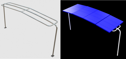
Solar Arch Installation
Installing the arch took me two days, only about twice as long as I planned. While the arch isn’t all that heavy, it is cumbersome to move around. Luckily I have an adequate trailer and two strong sons to help me get it mounted to the deck. Getting the arch set in place was a pretty straightforward affair. I looped the main halyard onto the center of the arch, tied a couple control lines at either end, and the three of us swung the arch out behind Kestrel’s stern and set it in place to the spots I marked when I built the mockup.
After I got everything lined up nicely, I marked the four holes for each base plate and drilled through the deck. Easy so far, but now came the lazaret work. I’m really thankful my sons were along because I’m not sure I would have been able to pull it off. Getting the aluminum backing plates installed on the underside of the deck required the installer to hold themselves at an angle of about 30 degrees to the horizontal with one arm while reaching up over their head to install the plate and nuts with the other hand. Imagine if you will doing an extended one-arm plank while using fine motor skills to put a plate on four bolts and then put washers and nuts on with one hand. Sounds pretty horrible doesn’t it? It was…for them.
So aside from the gymnastics required, the process we followed was:
- Line up the backing plate under the base plate then mark and drill the first hole.
- In the lazaret, mount the plate on one bolt and line up as best as possible with the other bolt holes. In retrospect, we should have used the bolt holes to draw some guidelines to help with alignment before attempting this. We were basically guessing at the alignment using the distance to the hull as a guide. One we got one pretty close, but the other definitely is not square.
- Once the plate was bolted in place using the first bolt, I used the drill to mark the other three holes, making a good start on it as a drilling guide.
- Back in the lazaret, we removed the plate and brought it on deck to drill. For all of the holes through the backing plate, I drilled slow and used plenty of oil to keep from burning out the bit. One other thing to note here. Because these holes through the deck were hand drilled, they varied somewhat in angle. Same goes for the holes in the backing plates. When it came time to mount the backing plates I wasn’t able to get all four bolts through the holes. What I should have done was to drill the holes in the backing plates a couple bit sizes larger to accommodate the inaccuracy of my hand drilling. This would have saved some plank time for my sons as they had to attempt mounting the backing plates multiple times until I got it right. I’m not a machinist and don’t play one on TV, but I’ve done enough of this sort of thing to know better. Needless to say my boys were not happy with me at all.
- The arch was designed to pass the electrical cables from the panels inside of the tubing of the arch and through the deck. That meant I needed to drill a hole in deck corresponding to the 1 1/2” diameter of the tubing. This was pretty simple once I drove to the local hardware store and got the right sized hole saw. Unfortunately I also had to drill the same hole in the backing plate. You guessed it, one of my helpers had to mount the backing plate so I could get the hole drill point marked correctly. I wasn’t sure how well the saw was going to work on the aluminum plate, but it did a pretty good job. I’m not sure if the saw is going to work on anything after that, but mission accomplished.
- The last bit of work before bolting everything in place was to drill the deck core out from the mounting holes in the deck and fill them with epoxy. I picked a size bit to give me a decent amount of epoxy around the perimeter of the hole to seal the core from any water intrusion. The drilling was accomplished from the underside of the deck, just up to the bottom side of the fiberglass (sorry boys). We put a piece of tape across the bottom of the drilled out hole and I filled the hole with thickened epoxy. We actually got all of this done by mid afternoon, but couldn’t move any farther forward because the epoxy took its time to cure. The next day, we trekked back to the boat to finish the job.
- After all of this prep work, bolting the arch in place was simply a matter of applying the sealant to the bottom of the arch and mounting the backing plates with nuts and washers. I used butyl tape between the deck plates and the deck and on the backside of the screws to provide the seal. This stuff is super easy to work with and stays flexible and seals for a very long time.
- But wait, there’s more! The arch was designed to have a diagonal strut from the arch to the stern pulpit rail. The fabricator provided me with the clamp mounts for the arch and stern pulpit as well as a length of stainless steel tubing for the strut. Mounting the strut was a simple matter of installing the clamp mounts, cutting the two diagonal struts with a hack saw, and installing the struts into the mounts. I was pleasantly surprised to see how stable the final product is.
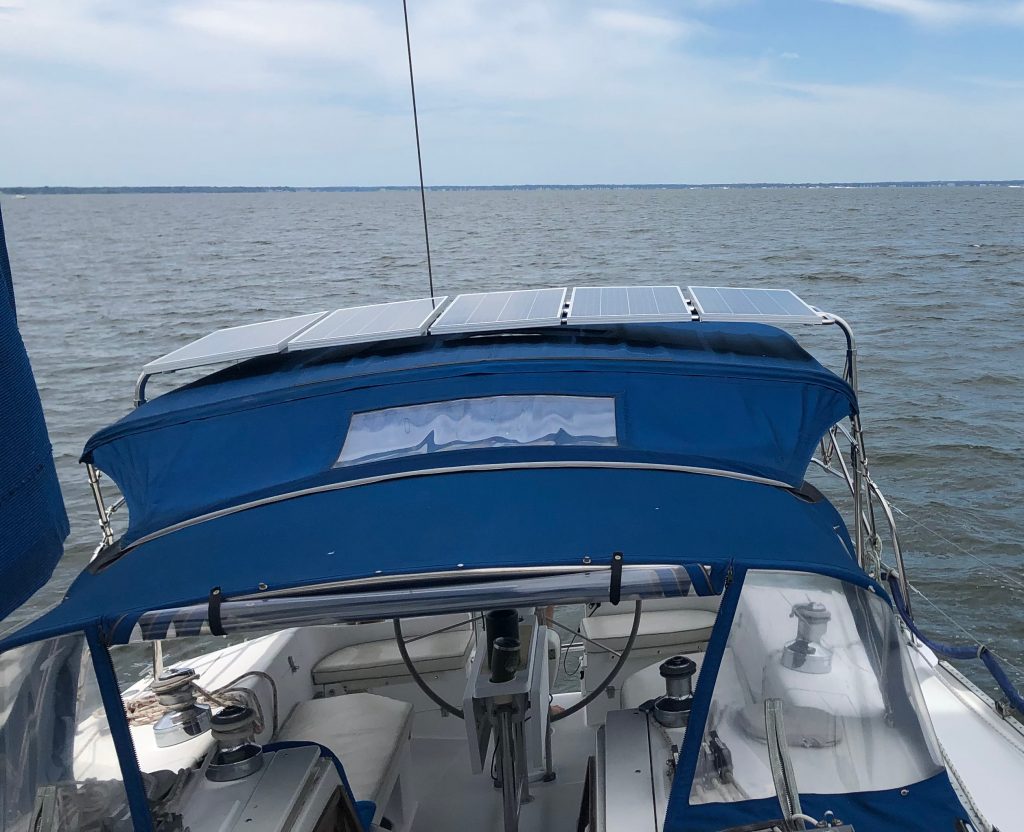
Solar Panel Installation
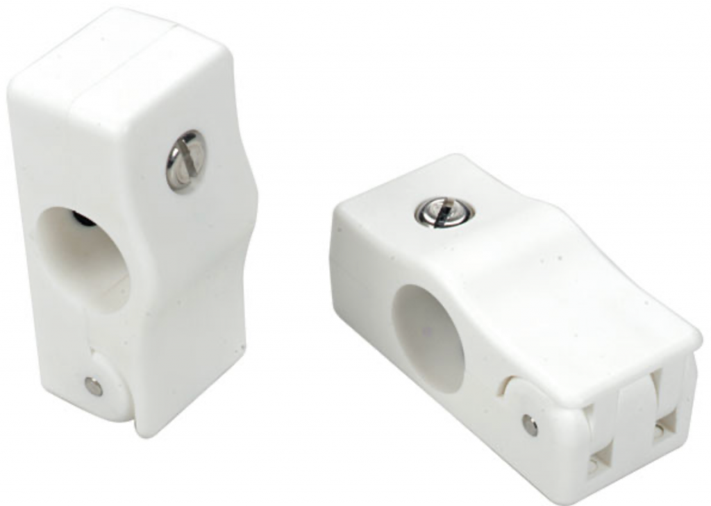
There are a few ways to mount panels to an arch. I could have had the fabricator weld tabs to the arch, but didn’t want to tie myself to fixed locations and panel sizes so that I can adjust position or change panels in the future. I’ve seen where people have used u-bolts to mount panels as well which probably would have been a good, cheap solution, but I didn’t like the way it looked. I spent more money than I would have liked on the clamps below from West Marine. Once I got past the sting of the price, I was very happy the product.
I had the arch set up in my basement and did all of the fitting of the solar panels there. I lined them all up, made sure they were evenly distributed along the arch, and marked positions with a Sharpie. I took the clamps, attached them to the arch at four places for each panel, marked the locations on the panels, and then drilled and attached the clamps to the panels. With the clamps already attached to the panels and the panel locations already marked on the arch, installing the panels on the arch was literally a 20 minute job once the arch was installed on the boat.
Switch Box Installation
When I did my survey for the electrical panel, I found a good spot to mount the switch box. There is a shelf that runs right above the panel location and the underside of the shelf is the perfect place for the switch box. Mounting the box was just drilling four holes in the plywood shelf and putting the screws in. The way I built the box, the switches mounted in the long side of the box itself and the box mounted with the lid facing down to provide access to wire the switches.
Solar Panel Wire Installation
I used the duplex cable shown in the previous post to provide the connection between the solar panels and the switch box. I fished a string from the access ports on the top of the arch down through the port side tube and through the deck and used the string to pull each of the five cables from the panels to the switch box. I terminated the switch box end of the cables first, using the Vertex female disconnect connectors. Then I terminated the solar panel end of the cable using the MC4 connectors that matched those preinstalled on the solar panels. This order is important to make sure you don’t have power on the switch box end of the cable when installing the connectors there. Once everything was hooked up, I got out my multimeter to check voltage polarity at the switches and to make sure I got the switches wired correctly so that off means off. While this operation sounds simple, it was time consuming to pull five cables, install 20 terminations, and tidy it all up with wire ties. This took me most of a day.
Electrical Panel Installation
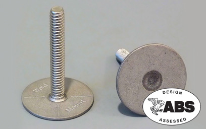
The spot I found for the electrical panel was directly on the inside skin of the hull. Obviously, I wasn’t about to put any screws into my hull. I initially thought about installing wooden mounting blocks using epoxy and fiberglass mat. While I was looking for sources for those materials, I ran across Weld Mount products. They supply super strong acrylic adhesives and mounting studs. I selected the AT-1030 adhesive which comes in a small quantity useful for this sort of installation. I used six of the stainless steel studs and made spacers out of the same 1” HDPE rod I used for the bus bar shield standoffs. In order to get a solid surface for gluing the studs, I sanded the landing locations for the studs down to the bare fiberglass. I didn’t have a good way to hold the panel in place while the adhesive for the studs cured, so I took an incremental approach. I glued the top right corner stud in place, holding it on the sloping surface with a couple strips of tape. After letting it cure for about 40 mins, I fitted the panel onto the mounted stud and marked the position of the top left stud. I glued that one in place with tape holding it as well. After letting that one cure for about 40 mins I attached the other four studs to the panel, applied adhesive to each, and hung the panel from the two mounted studs, pushing the four new studs into place. No tape was required for these. I let the studs cure overnight (probably not necessary) and put the nuts on the next day, securing the panel in place.

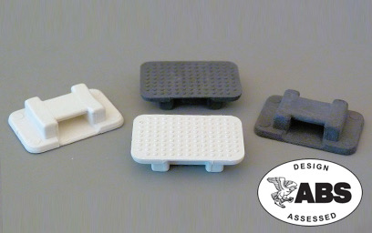
I also used some of the wire tie mounts below to for cable strain relief using the same tube of adhesive as for the studs.
Switch Box to Electrical Panel Wiring
With all of the switches turn off, I ran the same duplex cable from the switch box over to the electrical panel, terminating the switch end with female disconnect connectors. For the electrical panel end, I wired directly into the charge controllers. It is very important here to not apply any power to the solar panel inputs on the charge controllers before making the connection to the batteries. For the Victron units, this will damage the controllers.
Electrical Panel to Battery Wiring
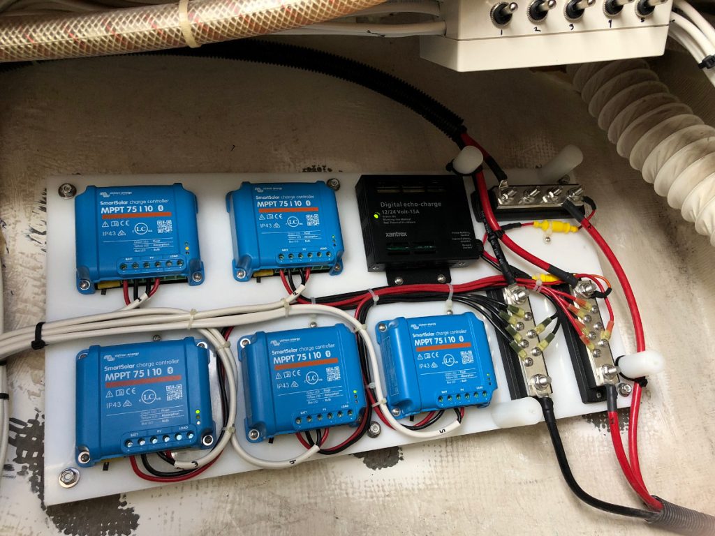
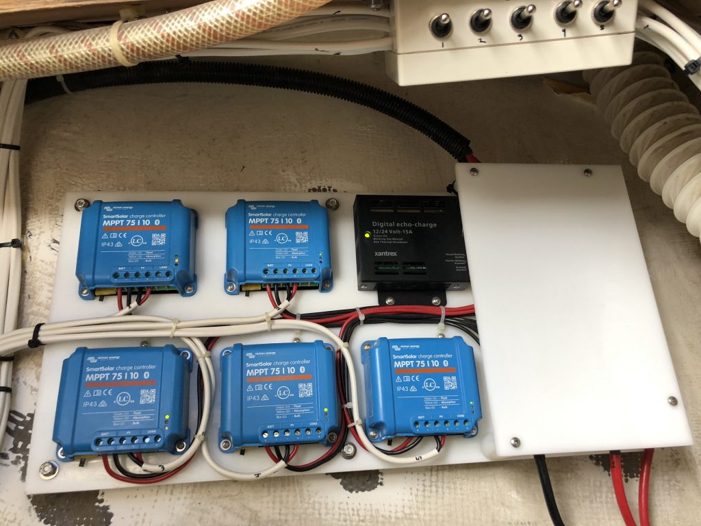
Remember that I told you there was a major advantage to the location I chose for the electrical panel? The big reveal here is that the wires going from the AC charging unit are directly adjacent to the new electrical panel. That means all I had to do to get the connection made to both battery banks was to remove some wire ties, cut three wires, put six ring terminals on and connect them to the appropriate bus bars. I didn’t have to run any wiring from the lazaret into the port aft cabin or, even worse, all the way to near the mast for the windlass battery. In the picture below, you can see the cables coming in from the switch box (top right) on the left side of the panel, running to each of the charge controllers. You can see the three wires from the AC Charger coming down from the top right, connect to the three bus bars and then continuing in their way from the bottom right on to the batteries. The second picture shows the panel with the bus bar shield in place.
Commissioning
The process of building and installing was done over the entire winter, spring, and summer of 2019. I work full time, have a bunch of cars and a house to take care of on top of Kestrel, so I worked it a bit at a time. There really was no hurry as the solar charging system wasn’t essential and I wanted to sail. I picked weekends when there was no wind or no crew to work through the project and didn’t finally do the final hook up until the fall, after my last sail. My commissioning process went something like this:
- Downloaded and installed the app to my iPhone and made BlueTooth connections to all of the charge controllers. Once they were connected to the batteries, they were live. Each charge controller needed a firmware update so it took a little time to do that for each one. It was a simple process, done through the app.
- Switched off the AC charger.
- Turned on solar power to one charger at a time and watched the charge controller behavior on the app. This allowed me to determine which charge controller ID mapped to which solar panel switch.
- Once I was satisfied that all of the panels were getting power and able to provide a charge individually, I turned on the entire bank. I monitored the behavior of all of the chargers. This meant hopping back and forth between the charge displays in the app. It would be nice if the app could provide a dashboard of all of the chargers, but it doesn’t.
- Once I saw that all of the controllers were working together, I applied a load. I started with some lights, but those LEDs don’t draw much power. I know my refrigerator is a pig so I turned that on. I watched charge controllers cycle through the different charging stages as the batteries were drawn down by the load and then replenished by the solar panels. I was only able to test for a few hours before the sun angle dropped to low, but my overall impression is that the panels should be able to keep up with the load while I’m sailing or at anchor. Now the question is, will the system be able to replenished the batteries drained overnight by the refrigerator during the day while it is still running. My power calculations tell me that it should be able to do this, but I’ll not know for sure until this summer.
If you’ve made it so far in your reading, I applaud your tenacity. You my friend are a true boat nerd. As always I welcome questions or discussion so feel free to leave a comment.

By far the best install post I’ve seen on these, will be extremely helpful to DIY.
Thanks Doug, that is high praise indeed. I’ve been very happy with the fit and finish of the arch as well as the performance of the charging system.
Terry
Terry,
Excellent write-up! I will soon be working on a solar upgrade to my Catalina 36 and your articles have provided a wealth of insight. I was wondering if you have any follow-up thoughts on this project? Also do you have any more pictures of the solar arch (pre and post install)? It’s a very cool idea to blend a bimini and a support arch with kickers back to the push-pit. I look forward to future blog posts!
Thanks!
Mike,
Thanks for the comment. I’ve been very happy with how the system functions overall. It achieved my design goal of being able to maintain charge during the day while sailing and recharge mostly by mid-morning after a night on the hook with the refrigerator running. My refrigerator does run down the house bank overnight, just to the edge of where I would be concerned about battery life, but I’m actually having an issue with it that makes it run significantly longer than it should. Once I sort that out I expect the battery level to be much better in the morning.
As for more pictures, I actually can’t find any of them which is odd as I seem to take pictures of everything. I’ll capture some next time I get down to the boat and email them to you.
Terry
Terry, are you in the Hampton Roads area? I also have a 42 and would like to see your arch setup.
Jeff,
My boat lives in Colonial Beach on the Potomac. I’d be glad to show you the arch if you want to make a trip up that way.
Terry