
Solar Charging System Post #3 – Charging System Design
There is a lot more to building a solar charging system beyond the panels and mounting hardware. You can think of the overall system as a three legged stool. The first leg is the energy source side, the panels and how they get mounted to the boat. The second leg is the charging system that converts the raw electricity provided by the panels into something that the third leg, storage, can use. This post is going to address selection of the charging system components and design of the charging system electrical panel. Yes, another exciting and heady topic for all my fellow boat nerds out there.
Solar Charge Controller
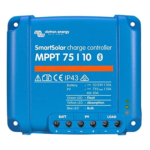
I’m not going to even attempt a lesson in the different options for charging here. From my limited research, two different types of chargers end up at the top of the list, MPPT and PWM. The former is a newer, more efficient technology and the latter older and less efficient. Keep in mind that they both work. If you read my post on LED replacement, you’ll know that I’m all about efficiency, so obviously I went with an MPPT controller. There are a number of manufacturers that sell MPPT controllers. I looked at a few and decided on Victron. There are a couple of features that made me lean towards Victron. First, the unit I selected has a BlueTooth capability, so I can check status and charging history from an app on my phone or tablet. This is a very powerful tool and doesn’t require extra cables or display. Second, these units work together seamlessly when connected to a common storage bank. This is important to me because I went the rather expensive route of having a dedicated charge controller per solar panel. There can be problems when connecting multiple panels to a single charge controller. If one of the panels gets shaded, it can reduce or negate the power from an unshaded panel. There is no danger here, just loss of charging capacity. Considering that these panels are on a sail boat with a rather large mainsail in proximity, there is a good chance it will throw shade on some of the panels while underway. I wanted to make sure I could get as much juice out of them as possible. The specific unit I chose was the Victron SmartSolar MPPT 75/10 Solar Charge Controller 75V 10A with Bluetooth. I had room for five 100w panels on my solar arch, so purchased five of these controllers.
Switch Box
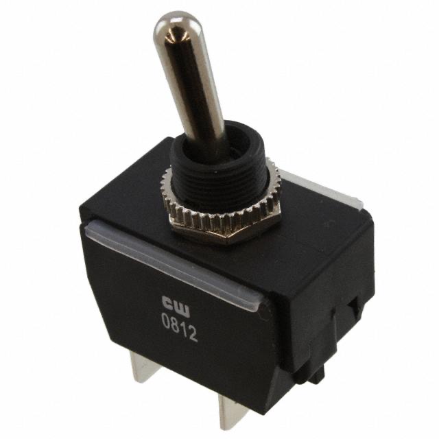
While thinking about how I wanted the system to operate, it became clear that I needed to have the ability to remove power from the input side of the charge controllers, to break the circuit between the solar panels and the controllers. This would allow me to work safely on the charging system and turn off solar charging while at the doc and plugged in to shore power. I built a switch box with five double-pole, single-throw switches that I sourced from Digikey.
I got a project box like the one below that measured 6.2”X 3.54” X 2.51” (158mm X 90mm X 64mm) and mounted the switches in one of the long sides. The number of switches will dictate the size of the box of course. I put in a link from Amazon, but they don’t seem to carry that specific size as of this writing.
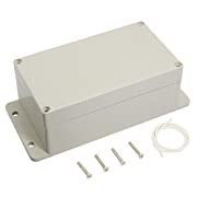
The mistake I made was to try and route the wires into and out of the box from the ends. While this just worked, it was difficult to make the wires fit with the connectors that I used. If it weren’t such a pain, I’d redo the box and bring them in from the long side opposite of the switches.
Windlass Battery Charging
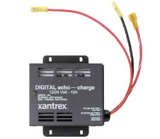
There is one other factor I had to account for in the design of my charging system, the windlass battery. My house bank consists of two 4D batteries, and I’ve got an additional 4D battery for the anchor windlass. The two banks are physically separated by more than ten feet so I can’t just connect them all together as they would discharge into one another leading to premature failure. I did want to be able to apply some charge to the windlass battery from the solar panels however. The solar charge controllers I picked are able to charge to a single storage bank, so I had to find a way to provide charge to the windlass battery while keeping the banks isolated from each other. I found a unit from Xantrex called an Echo Charge that fit the bill.
Charging Circuit Design
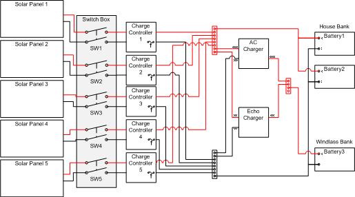
With all of the major components identified, I drew up the circuit diagram to give me a guide on building the electrical panel. My original design was done in pencil and changed a bit when I discovered the charge controllers had integral fuses. I had planned to have a fuse block between the charge controllers and the positive bus block but decided that was redundant. Unfortunately I already purchased the fuse block, so that is sitting in my garage with my miscellaneous boat parts. Rather than breaking out the eraser and pencil, I fired up my copy of Visio 2007 to find that it still works and cranked out the diagram below. A few of points about the diagram. First, you may notice that the batteries aren’t fused. This is not a mistake on the diagram, my batteries are not fused…yet. Phase II of my electrical upgrade is to add power monitors and fuses. This will be accomplished as funds and time allow. Second, I don’t show the AC wiring for the AC charger. I thought it would just confuse things. Third, I do have a battery switch (1/2/All/Off), but the charging system bypasses the switch, so I don’t show it.
Wiring Components
The wiring components are just as critical as the active electrical components. I’m talking about the wire, connectors, and bus bars. I did a lot of looking around for these as well and below you’ll find what I used. I have to say that I really like BlueSea components. Everything I’ve bought from them has been very good quality.
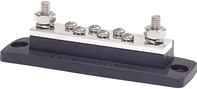
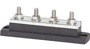
Bus Bars
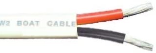
Wire
Remember, you need to use wire of the correct gauge based on the current load and length, that is stranded, not solid, and is tinned.
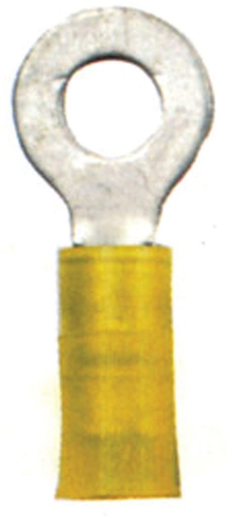
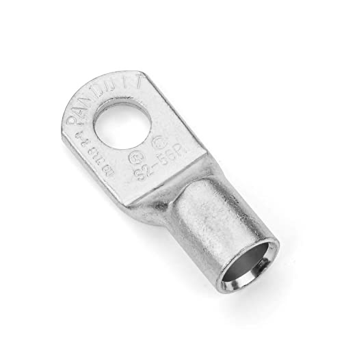
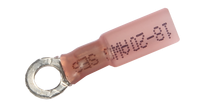
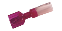
Connectors
I recommend buying the little plastic wrench set for the solar panel connector. It really makes assembling the connectors a snap.
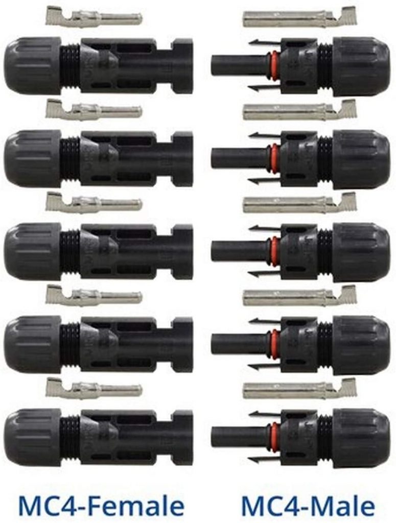

Vertex Marine Connectors
Vertex Marine US Distributor – Greg Anixter, Trillium Cable
Building the Panel
I surveyed various spaces where I could install the panel. There is a nice space adjacent to the house bank, but is under the aft port berth. The charge controllers will generate heat and need some air flow for cooling. Under the berth was not going to work. I found a couple good spots in the port lazaret and decided that I would mount it to the hull, under a shelf. There was a major advantage to that location which I’ll discuss in the next post about installation. The reason I bring it up here is that the space available defined the size and shape of the electrical panel which drove the layout.
I went around and around for a while on what material to build the charge controller electrical panel out of. I thought about aluminum and plywood, but eventually settled on High Density Polyethylene (HDPE ) panel. This is the same material you may be familiar with as Starboard. I found a source on Amazon that sold it in small sheets at a not ridiculous price. The material I picked was a little cheaper because it wasn’t rated for exterior use and doesn’t have UV inhibitors. This is fine as the panel lives in my port lazaret. If it gets exposed to a lot of sun, I’ve got much bigger problems than panel degradation.
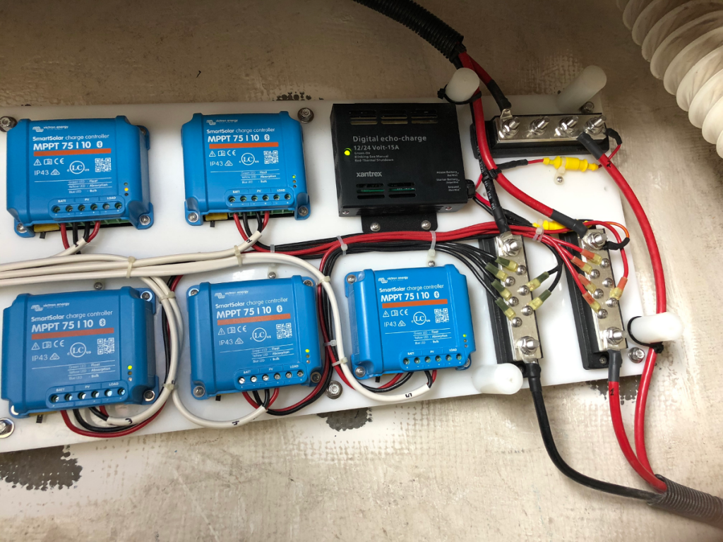
I went with a 1/2” thick panel which provided a nice solid base for the components, but still had a little flex for mounting. I didn’t try to do a physical layout of the panel on paper, but just got all the components and located them on the panel with an eye toward component fit, spacing, and wire runs. I wired everything I could ahead of the installation in the relative comfort of my garage. I had been worried about how to protect the bus bars from inadvertent shorting by objects that might end up rolling around the lazaret while underway, so I laid out the panel with all of the bus bars at one end and built a shield from 1/4” HDPE sheet using 1” HDPE rod for standoffs.


Unfortunately, I didn’t capture any pictures of the panel as I built it, but I did take a few while installing on Kestrel.
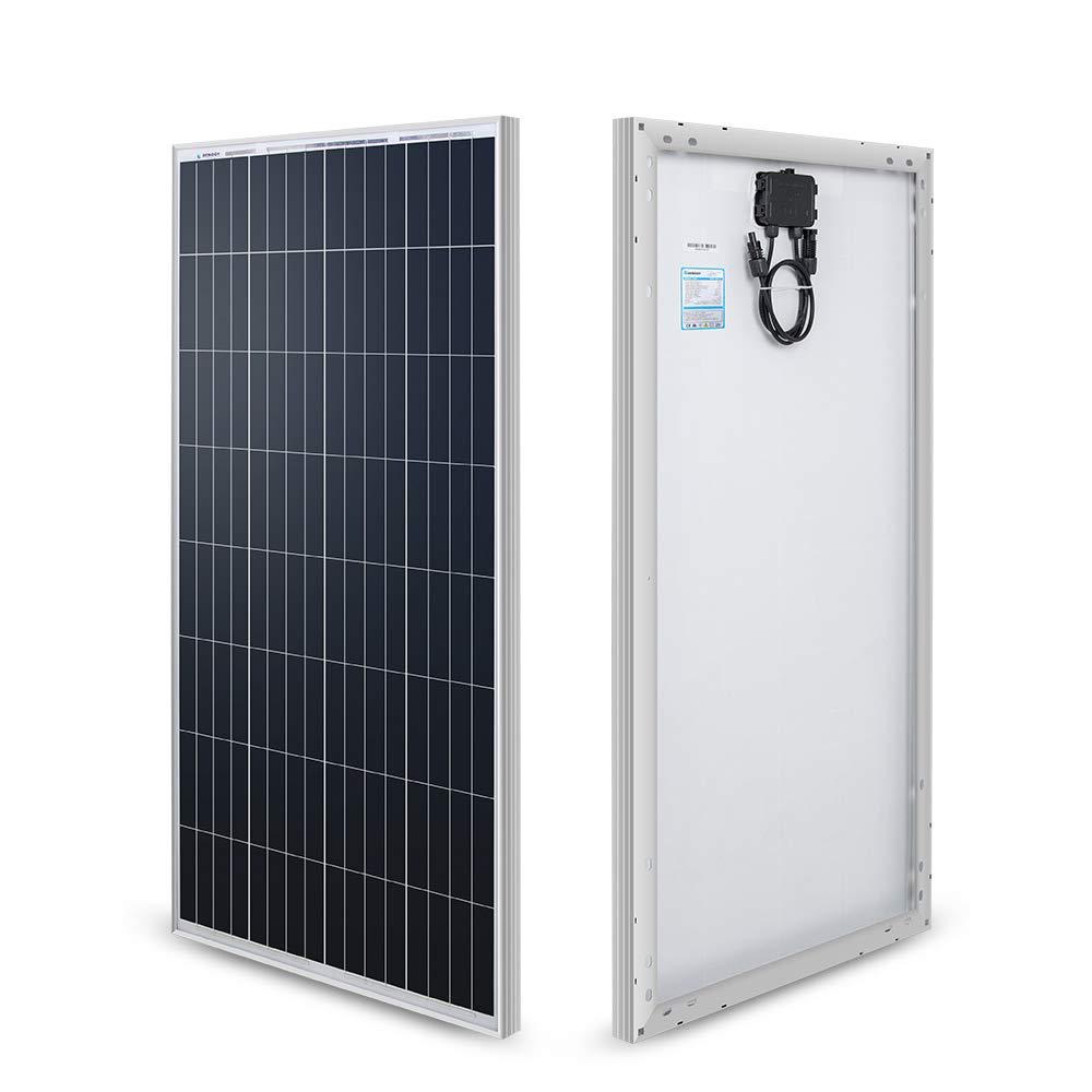
Solar Panels
I got all the way to the end of this post and realized I hadn’t talked about the solar panels. The choice of solar panels was limited to what I had room for on the arch. I chose 100W panels from Renology. The dimensions of the panels allowed me to mount five of them on the arch with just enough clearance between the boom and the back stay. I could have selected longer panels for the port and starboard panels, but I didn’t like the look of that. I may change my mind in the future if my charging capability doesn’t keep up with demand. I order the panels from Home Depot as they were a little cheaper than Amazon at the time. It is interesting that the cost has gone up about $20 a panel in the past year. I’d guess that tariffs had something to do with that.
Next Up
I think I covered everything that went into the design and build of my solar charging system. I carefully climbed that hill, but from the top I could see the next hill, installation. In my next post I’ll walk through the steps I took to get the arch, solar panels, and electrical panel installed, wired, and tested.
This looks great. Does your echo charger charge off the bigger bank?
What will you do in case of a wind event like a tropical storm@? Can you easily take off the panels and stow them?
Are you using AGM?
Chef,
The echo-charge senses when the main bank is being charged and pulls current off to direct it to the windlass bank. The bits below come from the product web site and manual.
Xantrex’ digital echo-charge (part#82-0123-01) is designed to charge auxiliary or starting batteries from an inverter/charger or other charging source with limited voltage drop. The Xantrex echo-charge detects when the house battery bank is being charged and directs a portion of the charge current to auxiliary or starting batteries. The maximum charger current offered by echo-charge is limited to 15 amps.
The Digital echo-charge is a voltage-follower, following the three-stage charge modes of the Freedom Charger. This method protects the starter battery from over-charging and ensures a long life for the battery. If using another charge source, the Digital echo-charge will follow the charge stages of the source. Refer to the source’s Owner’s Manual for charge modes.
Regarding removal, the panels are clamped on with four screws each (see new post #4) and would take me about 20 minutes to pull off in case something big makes its way up the bay.
Finally, I replaced the flooded cell bank that came with the boat last year with Lifeline AGMs. I tested the system out last weekend and was pleased to see that the panels kept up with the load plus had enough juice to recharge the bank fully after an overnight running the refrigerator on a partly cloudy day. It also topped off the windlass bank to boot. The panels just barely kept up with the load on a heavily overcast Sunday though. I feel that I would end up running the engine to charge at some point in those conditions. The jury is still out though because it was cool and I’m don’t know how it will behave when the refrigerator is trying to work in summer heat. We shall see.
Terry