
Solar Charging System Post #2 – Measuring for the Solar Panel Arch
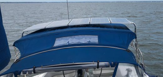
In my last post I talked about how I got to the decision to mount my panels on a dedicated solar arch. The next step was to refine the design of the arch to get the dimensions and angles for the fabricator to use in the build. The process will be pretty much the same no matter who you have build the arch unless you can get them to come to the boat and measure for you. I couldn’t find anyone local and didn’t feel like sailing all the way up the bay to Annapolis, so it was up to me. While I’m certainly not a marine professional, I’m fairly handy so I was up to the challenge.
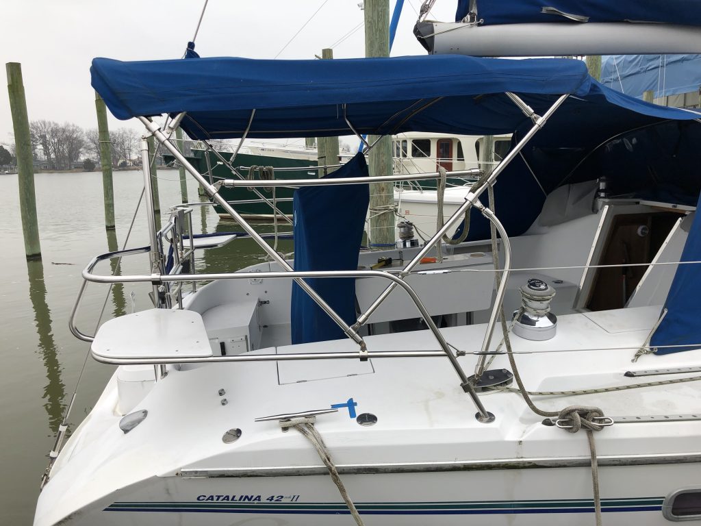
The first thing I had to figure out was where on deck I was going to land the pads at the base of the arch. They had to be placed on the port and starboard coaming so that the arch would cross near the middle of the bimini between the end of the boom and the back stay. It didn’t have to be perfect, but close. They also had to be placed such that I would be able to work below deck to get the backing plate on the underside. On Kestrel, I found that I could land the pads pretty much in line with the base of the bimini frame, very close to center. The trick though was that I would have to thread the arch legs through the upper cross brace and the two two diagonal support frames. You’ll see this further down. The deck under those spots was in the lazaret with no obstructions. The problem was that they were behind the propane lockers and would require some serious contortions to get the backing plates installed. I also had the option of removing the propane lockers if the boat yoga pose was impossible to hold. The blue X marks the spot for the starboard landing spot in the picture below.
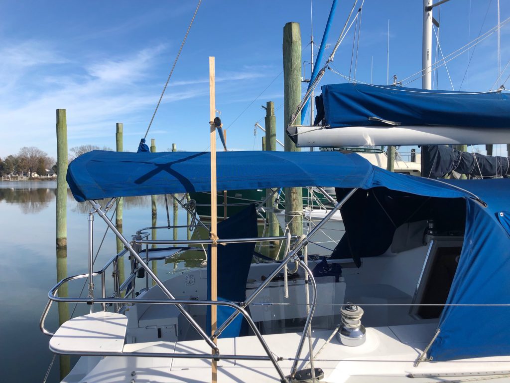
Now that I knew where the base of the arch was going to go, I needed dimensions. At the suggestion of my fabricator, I used a couple scraps of wood I had laying about, a boat pole, and some twine to make a rough model of the arch. I used my carpenter’s level to get the legs vertical. When I was happy with the height above the bimini and the placement of the legs, I measured the height above deck of the cross member. I had already measured the distance between the blue X marks. You can see in the picture below how the leg lines up with the bimini frame.
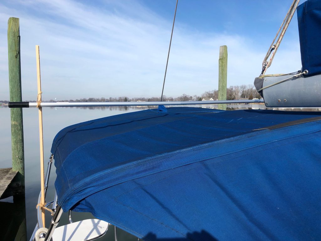
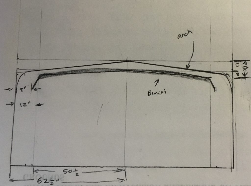
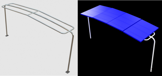
I also lowered the cross member to just touch the bimini and then measured the slope of bimini from the horizontal. This was gong to give me my angle for the top of the arch as I wanted it to mimic that of the bimini. Below is my hand scratched drawing of the final dimensions of the arch.
Those were the easy and fun measurements. What was not so fun was measuring the angles at which the pads had to be welded to the arch legs to match the slope of the deck. This one had me stumped for a while. On my first try, I set bits of cardboard on the deck and drew lines on them from the legs of the model arch I had built. I made sure the legs were true vertical and it seemed that this method would be a quite straightforward way of getting the angles. What I found was that I couldn’t get consistency in the angles I was drawing. When I went back and checked the measurements, they were off slightly. I tried multiple times, but never got to the level of accuracy I was happy with.
I went back to my fabricator and asked him how he took the measurements when he had access to a boat and he told me “there’s an app for that”. Now keep in mind that I have had a smart phone of one kind or another since they came into existence, and I have a pretty good understanding of the sensors that are packed into a modern phone, but it did not even occur to me to use a precision level app to make these measurements. There are quite a few free level type apps in the iPhone App Store and I’m sure many in the Android App Store as well. I looked at a few and settled on one called Precision Level – Spirit Level by a developer by the name of Robert Sniezynski. The user interface is quite intuitive and anyone who has ever worked with a level will figure it out in about five seconds.
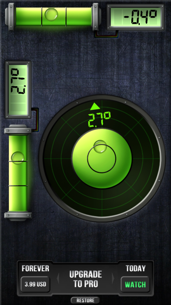
When trying to use a level on a boat a few important things have to be taken into account. First no boat floats perfectly level. Second, every time you move around your weight causes some amount of change to the attitude of the boat. Third, any sort of wave action at the dock will destroy your ability to get a good reading. After picking a calm, cold day when I figured there would be no boat traffic by my slip that happens to be right next to the channel that every boat in Monroe Bay has to traverse to get out to the Potomac and back, my first step was to take a baseline of Kestrel’s attitude. Using my phone and the app, I found what I considered to be the most level, flat part of the cockpit, the spot directly behind the wheel. I recorded about a degree of bow up and a half degree of starboard down. It was after this initial reading that it occurred to me that when I shifted over to the starboard side to take measurements at the blue X, Kesrel heeled a little to starboard under my weight. So I went back to my original position behind the wheel and set the phone on the starboard cockpit seat where I could read it from both behind the wheel as well as perched on the starboard coaming near the blue X. I took a reading while standing behind the wheel and then another while perched. The difference in the two numbers was the amount of heel I induced when I moved from center. I repeated the process on the port side. Now I had my baseline and offset measurements, I could finally get on with making the actual deck angle measurements.
As the deck slopes out and back where the blue Xs were located, I was extremely nervous about setting my fancy electronic gadget there on the smooth slope of the coaming. My crew and I have managed to drop a few items in proximity to the blue Xs and pretty much everyone of them has been lost to Neptune, so there was no way my phone was going there without a restraint. I happened to be digging around in a closet at home when I came across the perfect solution, picture frames. With the back and glass removed, and the judicious use of masking tape to attach them to the deck, the frames provided a set of phone safety rails. The only trick was to get the frames lined up as parallel to the centerline of the boat as possible. This was probably the least precise part of my measurement rig as it relied on my eyeball assessment looking aft down the deck from mid ships. In retrospect, a better way to align the frames would have been to put a pole between the two blue Xs and then squared them with the pole.
With the frames secured to the deck, the actual angle measurement took only minutes. So now I had the baseline, offset, and deck angle measurements all written down. How does that translate to the angles for the pads? Simple math my friend, simple math. While I was at the boat and could see everything, I was able scratch out the method where I would add or subtract the baseline and offset angles to the deck angle measurements depending on the side. For instance, the boat listed naturally to starboard and then my weight added more angle to that. Because the deck already slopes down in that direction, I had to subtract the baseline and offset from the starboard angle. On the port side I had to add the baseline and subtract the offset. I just took the fore/aft deck angle without adjustment. Measurements completed, I went home and sat for an hour checking and double checking the math. I nailed it while I was on the boat but sitting at my desk back home, I kept second guessing myself. Eventually I sketched everything out and convinced myself that my original method and calculations were correct.
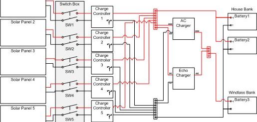
Once I was convinced I hadn’t screwed up the measurements in some fashion, I sent the package to the fabricator along with half of a bunch of money. This was in the early part of the year and I had plenty of time before spring commissioning and being ready to mount the arch, but there was still a lot of work to do while the fabrication was going on. I had to design the electrical panel for the charging system that would transform the electricity from the panels to something that could charge the batteries. We’ll get on that in my next post.
For anyone interested, my fabricator was Klacko Marine out of St. Catherines Ontario, Canada, close to Niagara Falls. Doug is a good guy and does quality stainless work. You can find the company at: https://klacko.ca
Great write up Terry, will be following along.
Appreciate kind words